I started this project as I wanted to explore ESP32-based IoT devices in a way that is applicable to the real world. Plant care provides a common context where automation is often useful to reduce water wastage and promote sustainable agriculture. Many people also live in environments with limited natural light, making it difficult to grow plants indoors.
To tackle this, I decided to design and build a smart self-watering plant pot that monitors environmental conditions and automatically maintains optimal growing conditions (e.g. suitable soil moisture levels and lighting). I additionally wanted to ensure the user can use an app to access real-time sensor data, manually control components, and set thresholds for automatic watering.
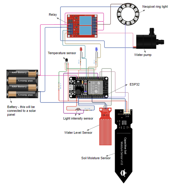
The system uses an ESP32 microcontroller to collect data from multiple sensors, including soil moisture, temperature, light intensity and water levels. The data is requested and stored locally and then made available remotely via a WiFi-enabled API for app usage.
System Concept
The system operates in two modes:
- Manual Mode: The user directly controls watering and lighting through the app
- Automatic mode: the ESP32 decides when to water based on user-set soil moisture thresholds
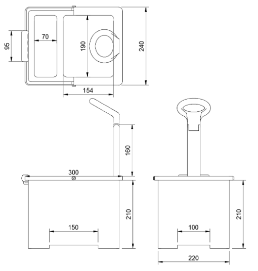
Physical Layout
The plant pot is divided into 4 main components:
- Plant and Soil Compartment
- This contains a soil moisture sensor probe and an irrigation dripper designed to be inserted into the soil to measure conditions and maintain correct moisture levels.
- Water reservoir
- This is located next to the soil compartment for easy access. It has a lid on top which can be removed for refilling and a submersible pump is placed inside which delivers water to the dripper when activated
- Electronics compartment
- This houses the ESP32 and the connections with the sensors as well. This is placed underneath the soil compartment and also allows access to replace batteries at the bottom.
- Growth Light
- This provides lighting for when the plant is indoors and in insufficient light (which can be measured by the light intensity sensor).
Design Iterations
This was my first iteration: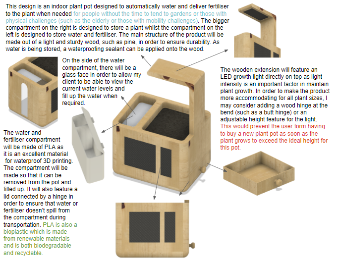
This design had several limitations:
- Fixed growth light position - this restricts the system to plants of a certain height and as doesn’t accomodate plants fo different sizes
- Limited water reservoir capacity - this could require frequent refilling
- Weight and Portability - while the system is inherently going to be heavy as it houses water and plants, features to make the plant pot more portable would help with transportation
Design Improvements
To improve the design I decided to look into adding three main features: a stand, a handle for portability and an adjustable light.
Stand
As the product will be designed for use both outdoors and indoors, having a stand on the bottom of the plant pot would allow for air circulation; this would help prevent the growth of mould, fungi and other pathogens that thrive in damp conditions. A stand would also allow for more mobility, letting the user manoeuvre the plant pot more easily.
My first design of the plant pot stand is shown below: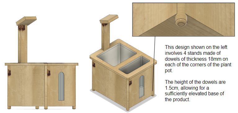
I realised that placing all the weight on four 18 mm dowels wasn’t ideal. From a manufacturing perspective, attaching four dowels to the corners could introduce structural weakness, since each dowel would rely solely on its bond to the base of the plant pot. Thus, I redesigned the stand to have a larger surface area and greater structural strength. Instead of being glued onto the bottom, the stand is now integrated into the wooden frame that forms the main structure of the plant pot.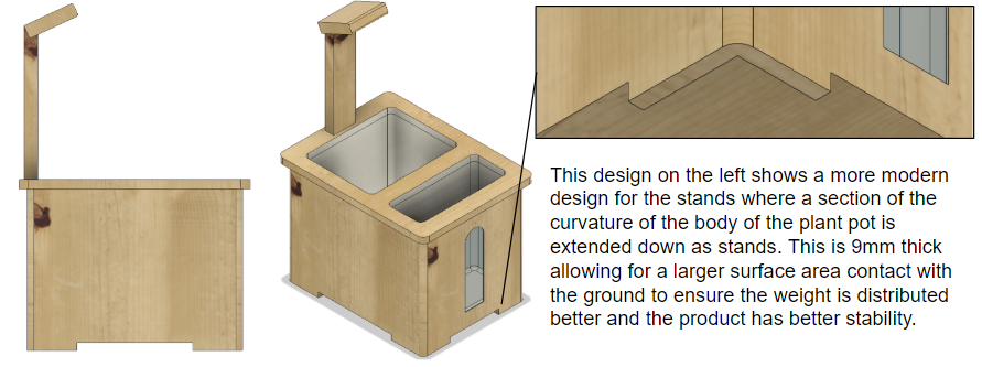
To verify the structural strength of the stands, I used Fusion 360’s simulation environment to perform a stress test on the stands by approximating the weight of the plant pot and applying this on the base of the plant pot. I found that the internal pressure with the second design was 2.5 times lower than the pressure with the previous stand design: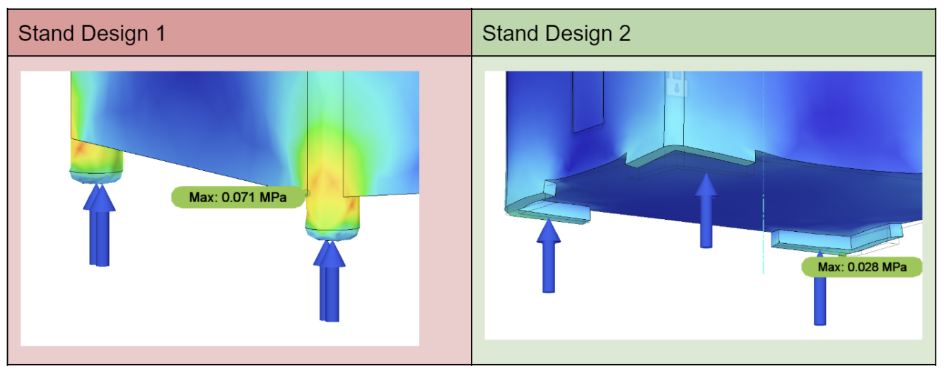
Thus, I decided to proceed with the new and larger stand option (Stand Design 2).
Handle
I also decided to add a handle to the design.
My initial design is below. This involves a handle on either side of the product. I also considered the ergonomics of the handle by incorporating troughs to fit the shape of a human hand and adding fillet edges. 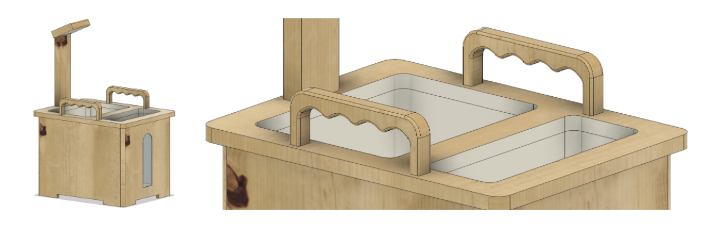
I once again performed a stress test to find the weak points of the handle. I placed a force on the underside of both handles to simulate the load of someone carrying the product. There was more stress on the corners of the handle and so I added extra fillet edges on the corner (shown in the picture on the right).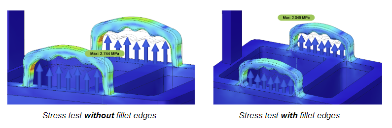
After some more consideration, I realised that although having two handles distributes the weight of the plant pot, this would be a slightly awkward configuration to carry the plant pot given that the width in this design is 24 centimeters. This would also make it impossible to carry the design with one hand.
I thus switched this design to have one large handle across the width of the product as it would allow the plant pot to be carried quickly in one hand. I used a swivel joint instead of statically fixing the handle to the top of the pot.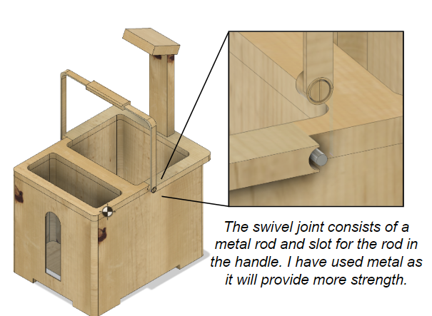
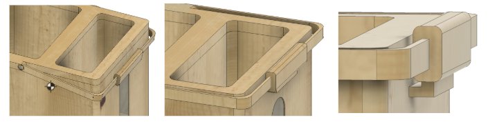
Although allowing the handle to rest on the body of the plant pot (left) would still remain functional, I designed a small catcher on the side (right) to keep it at 90° for symmetry when not in use.
 To evaluate the suitability of the handle material, I calculated the safety factor of the design. When tested using mild steel, the minimum safety factor was 2.546 and hence, the design would be able to comfortably withstand the load.
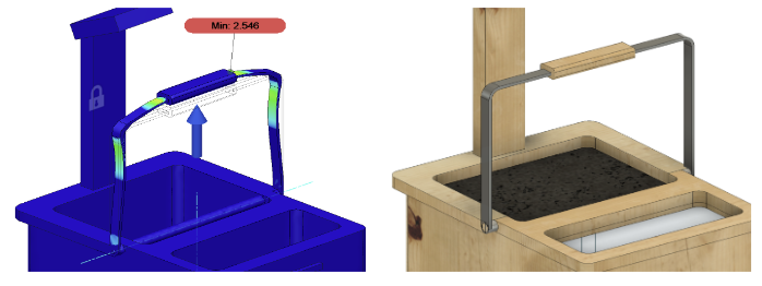
Handle Grip
I reintroduced the ergonomic grip on this metallic handle. To make an ergonomic handle that fits the anthropometrics of most people, I would need to use an accurate manufacturing technique like 3D printing.
I had experimented extensively with 3D printing filaments such as PLA before and although these could yield a smooth ergonomic handle with a comfortable grip, I wanted to experiment with different flexible filaments. These would allow for a more comfortable and would absorb some of the load, making it even easier for the user to manoeuvre the product. 3D printing the grip also allows me to experiment with different materials while also maintaining the accuracy required for the final product.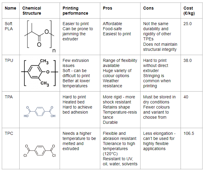
Although, given the pros and cons of the materials TPC seems like a suitable filament for the purpose of a plant pot, it is much less cost effective than the other options. Thus, I chose to print with TPU as it is still weather resistant, easily available and exhibits few extrusion issues.
To ensure the handle fits comfortably, I thought it would be useful to research hand anthropometric data. After looking through the data, I took out the key points that would be useful in the development of a handle:
The average grip width across both males and females is around 83mm.
The average finger width for both females and males is around 20mm.
I then incorporated this into my CAD drawings.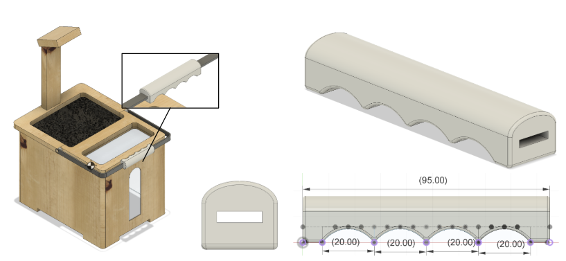
Growth Light
To encase the light, I included a torus shaped design for the casing as it can fit commonly-used Neopixel ring lights, which can function as growth lights at the right colour.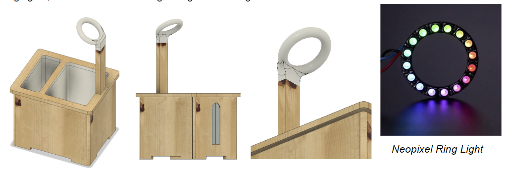
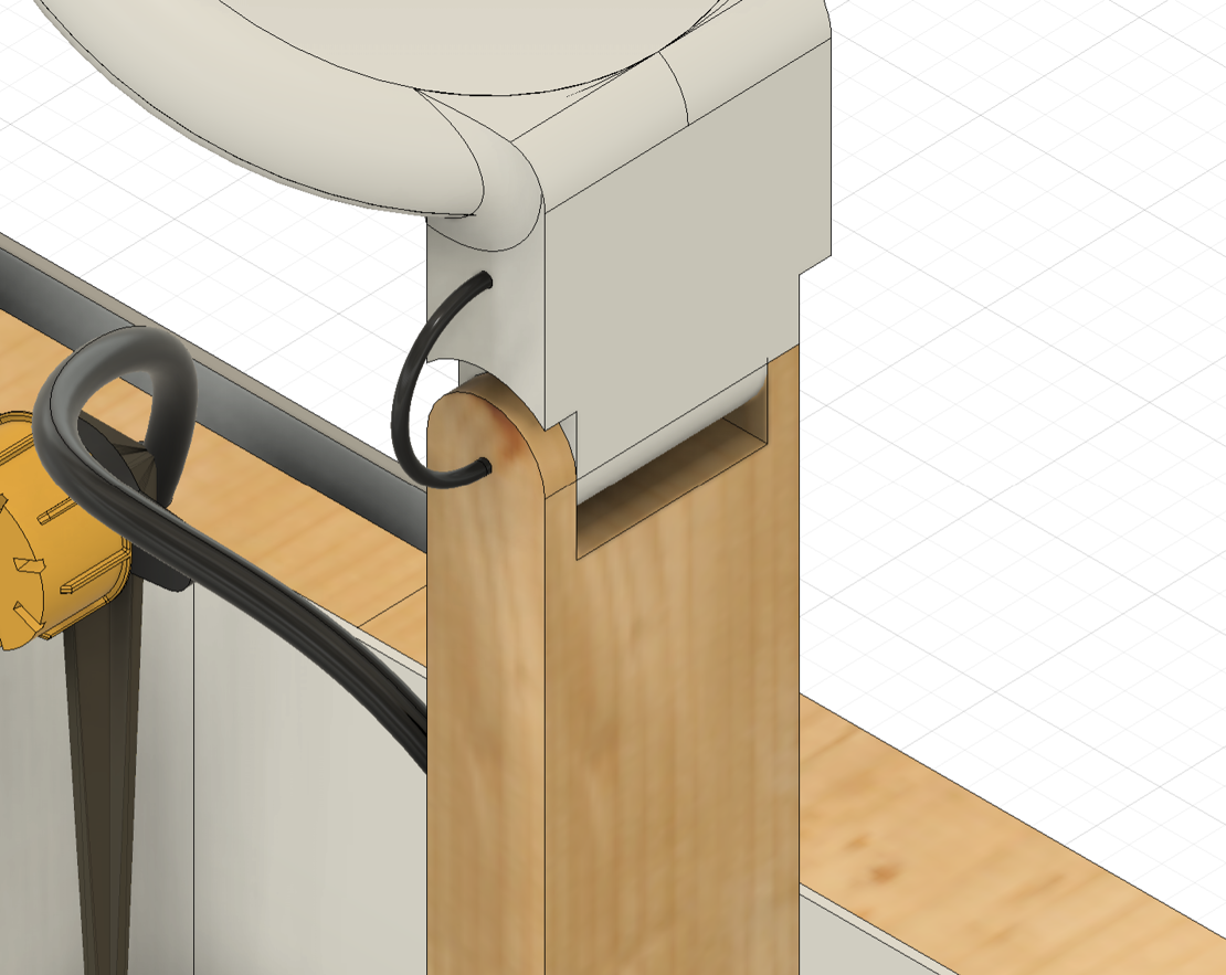
In the design above, the grow light casing is designed to be static in place and cannot be moved. However, this introduces height restrictions in this design as it may not be able to accommodate plants slightly taller than the height of the grow light. Thus, I decided to make the grow light adjustable at the joint between the 3D printed light casing and the wooden grow light arm.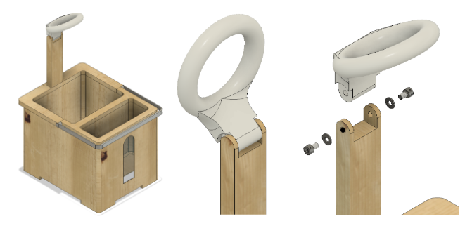
Thus, to make the light casing adjustable, I chose to make a hinge joint at the attachment between the wooden arm and the light casing. The wooden arm would include two 5mm thick shafts at each side that would allow the light casing to slot onto the arm. The tops of this wooden arm would be curved in order to fit the modern and curved aesthetic followed in the rest of the design. In order to make the design adjustable (rather than too loose where the light casing simply falls), I also chose to include spring washers as shown in the exploded view on the top right. I will also include very small tolerances between the wood and the casing (0.1mm on each side) to ensure both pieces fit tightly within one another.
Features and Functionality
Before building my final design, I wanted to go though the functionality I was aiming for to see which sensors and components I would need to accommodate in my design.
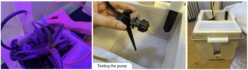
Water Pump
I decided to buy and test a vertical submersible water pump. I connected it to an ESP32 microcontroller. To be able to control the pump, I used a transistor as a switch and connected the base to a GPIO pin. I also included a diode in the circuit to prevent back electromotive force from the pump. However, this setup resulted in low water pressure which was not enough to push the water up from the water compartment. When I directly connected the battery to the pump, it resulted in a much higher flow rate, indicating that the transistor setup perhaps limited that current to the motor.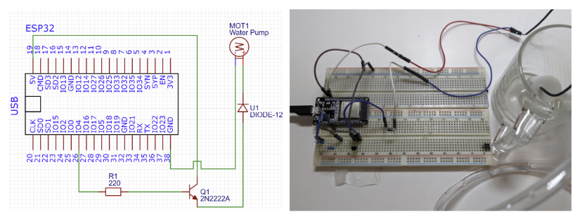
I decided to modify the power setup to include an external battery, connected through a relay, to power the water pump.
Moisture Level Sensor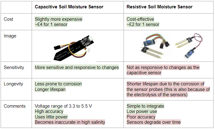
From the pros and cons highlighted above, I decided to use a capacitive soil moisture sensor as the high accuracy would allow users to get a better insight into the conditions of the plant.
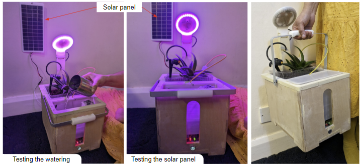
Light Intensity Sensor
To measure sunlight, I used the low-cost GL5516 LDR.
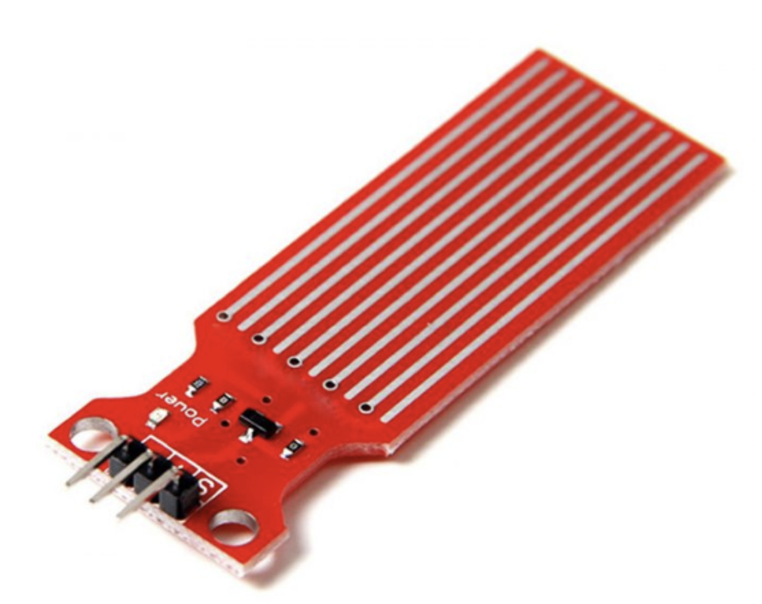
Water Level Sensor
To allow the user to get updates about the water compartment through the app, I initially used a capacitive water level sensor. The ESP32 can then inform the user (through a push notification) when the water has finished and when the user should refill the water compartment.
I later realised that this sensor didn't fit my needs. As it only measures water depth to a limited level, when fit at the bottom, it would only inform the user of the water level when it is near-empty.
VL53L0X_RangingMeasurementData_t measure;
lox.rangingTest(&measure, false);

int rangedist = measure.RangeMilliMeter;
Final CAD Design
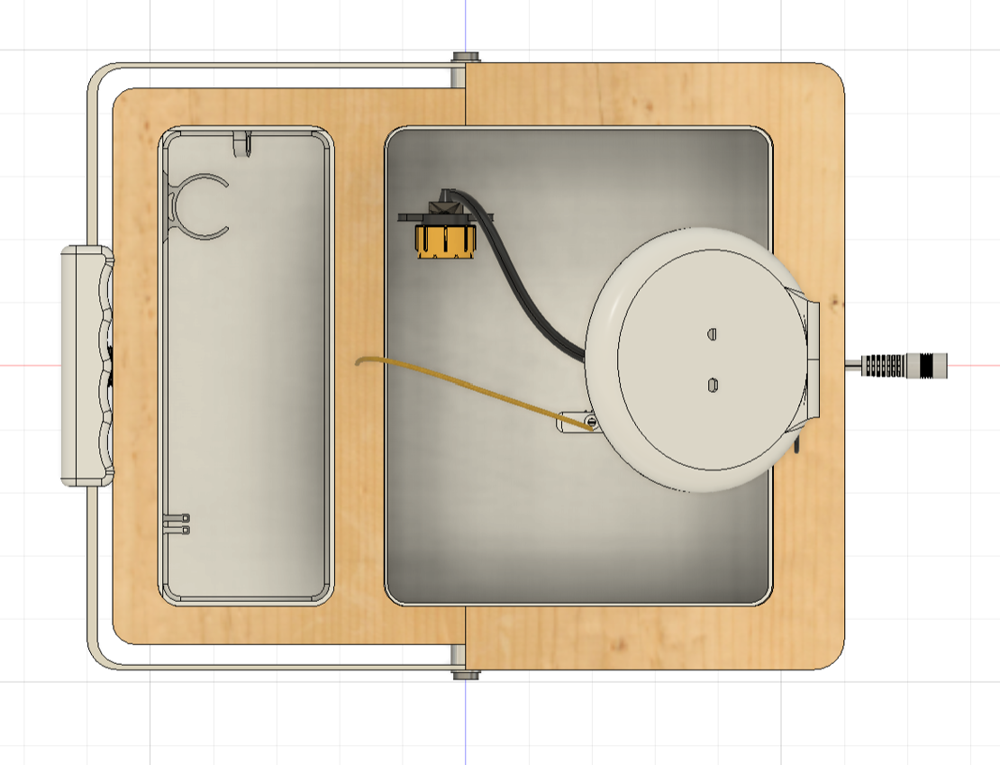
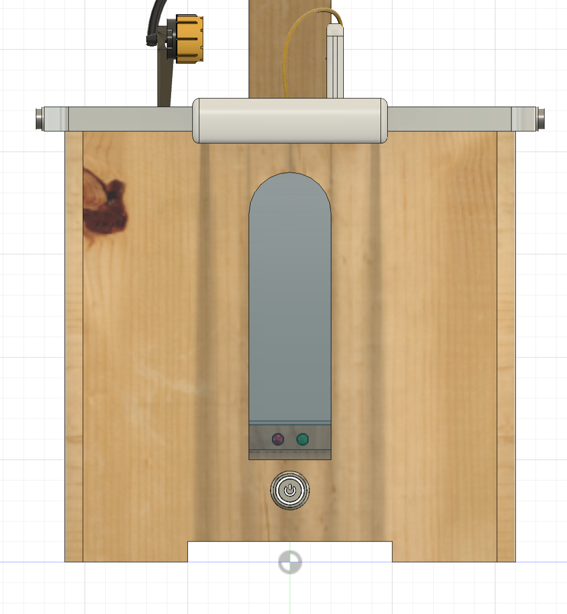
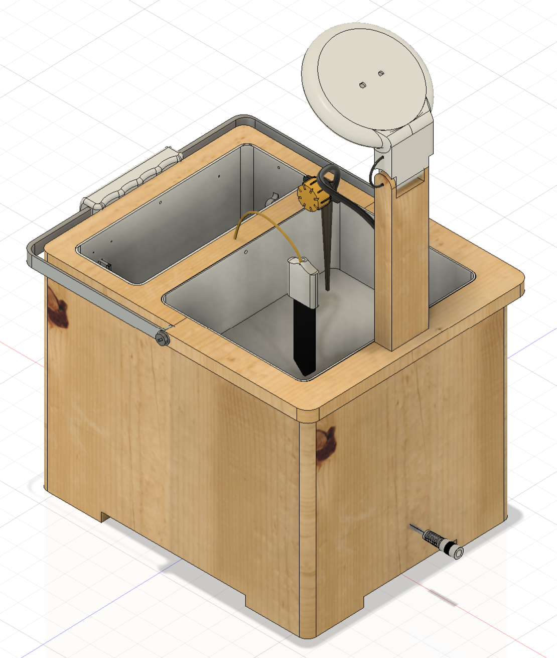
Now that I had all my components decided, I was ready to make my final CAD design. I show this below.
The final design showcases the growth light within a PLA encasing (which also houses the LDR and the temperature sensor) attached to the main body through a hinge joint. I also included the soil moisture sensor within its own encasing as well connected to the main pot with yellow wiring. On the side, I have included a water level viewing window, with RGB lights to show when the water pump is activated. Below these lights, I've placed a hexagonal press button which turns the whole system on. The water compartment also includes a water pump holder.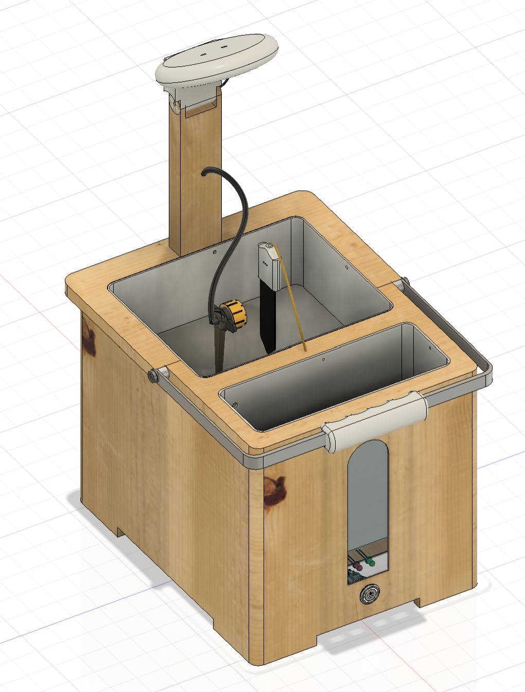
Circuit Diagram
Software Architechture
ESP32 and WiFi connectivityI chose the ESP32 built-in WiFi capability. On startup, the system attempts to connect to a saved WiFi network. If this fails, it creates its own access point for configuration.
WiFi.mode(WIFI_STA);
WiFi.begin(ssid.c_str(), pass.c_str());
This ensures the system remains accessible even in changing network conditions.
Persistent storage using SPIFFS
System state and configuration data are stored in flash memory using SPIFFS. This includes watering thresholds, automation state and light status.
writeFile(SPIFFS, motorPath, "1");
String motor = readFile(SPIFFS, motorPath);
This code writes the motor status to the ESP32's flash memory. This is accessed upon setup allowing the plant pot to recover seamlessly after a restart without losing user setting. I've written similar recovery code for the light as well.
REST API-based communication with App
The ESP32 hosts an asynchronous web server that exposes sensor data and control endpoints using HTTP. Data is exchanged in JSON format.
StaticJsonDocument<300> jsonDoc;
jsonDoc["soilmoisture"] = smpercentage;
serializeJson(jsonDoc, *response);
This is data is then accessed when needed by the app through the API.
To improve security, all API requests must include a valid API key in the request header.
if(req->hasHeader("API_Key")) {
  // verify key
}
Automatic Watering Logic
Automatic watering is controlled using upper and lower soil moisture thresholds. This prevents rapid on/off switching by changing the relevant status.
if (autowater2 == "1") {
  if (smpercentage < lowthresholdINT) {
    writeFile(SPIFFS, motorPath, "1");
  }
  if (smpercentage >= highthresholdINT) {
    writeFile(SPIFFS, motorPath, "0");
  }
}
This logic ensures water is applied only when necessary.
App
I have made 3 main pages in my app. These are shown below: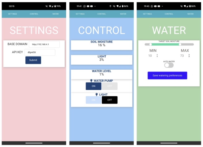
- Settings (pink screen): This view allows the user to input a base domain to which the ESP32 must send the requests and receive the data. This will be the domain the ESP32 is connected to on that specific network. The user must also send an API key. This API key will be checked against the API key stored in the ESP32. This ensures that only the owner of the plant pot can control the pot wirelessly, ensuring that the plant pot is secure.
- Control (blue screen): This screen is the main screen that the user will be on. This screen allows the user to receive sensor data (such as the water level sensor, light intensity, soil moisture levels). This screen will also allow the user to wirelessly control the water pump and the light, by turning them off and on.
- Watering (green screen): This screen allows the user to set their thresholds for the soil moisture levels that are needed to keep the plant healthy. This is shown through the green slider that is at the top of the screen. There is also an auto watering setting. When checked, this allows the plant pot to automatically switch on the water pump when the soil moisture readings fall below the lower threshold.
All code is written in HTML, Javascript and CSS. The code is converted to an app form through Cordova.
Challenges and Solution
One major challenge was the limited water level sensing with the capacitive water leevl sensor. I mentioned this above in the electronics section - my solution was to use a distance sensor at the top of a perforated tube in the water compartment.
My second issue was the ESP32 continuously resetting during testing.
This was quite frustrating as it was working well consistently during the prototyping stages. However, when the product was put together, this issue suddenly arised. Given this, I thought the issue may have been something due to the proximity of all the components. I realised this was due to brush arcing from the water pump. This can affect circuitry through both inductive and conductive coupling. Conductive coupling occurs when these EM pulses propagate along shared power and ground paths from the motor to the ESP32, while inductive coupling occurs when the rapidly changing magnetic fields around the pump induced voltages in nearby wire loops. The ESP32 RESET pin is a high-impedance input so these transients were sufficient to trigger resets. To fix this, I added an RC snubber circuit across the pump which absorbed the high-frequency voltage spikes. This solved the issue immediately
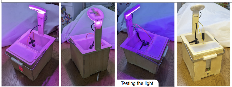
Final Product
The product was now finished!