This was one of my earlier projects and was my first dive into IoT projects. My aim was to make a desk lamp that is controlled using a wireless connection to a phone/computer, allowing a user to adjust the colour brightness and overall lamp status through a dedicated app.
I started out by making my first CAD iteration: 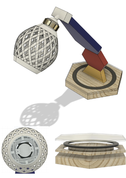
The curvature for this lamp would be created using a mitre joint. I would cut out the hexagons and then use a mitre saw to achieve an angle of around 12° on both shapes.
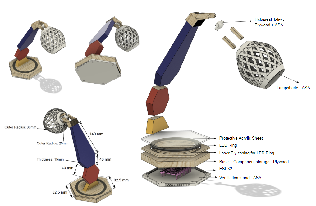
I intended to include a ball and socket joint (3D printed) at the top of the support. Using the ball and socket joint, users can easily adjust the angle of the light, increasing the functionality and allowing easy use of the product. In the 3D printed lampshade, I would include a compartment for the lights that I have soldered.
I intended to place dowels within the structure of the lamp to increase the sturdiness. In addition, I would drill holes in the middle of the frame of the lamp to make space for an electrical wire to supply current to the main lamp.
The base of the lamp houses the LED ring light that will be controlled through the mobile app and the ESP32 that is going to be placed within the base hexagon.
Pros of this design:
- The ball and socket joint meets the functionality requirements as it allows for easily adjustable light angles
- Portable and lightweight design due to the materials used (plywood, acrylic and PLA)
Cons of this design:
- Will be difficult to manufacture due to the complex structure (difficult to place dowels between the hexagons)
- No space for a battery compartment within the base. Thus the lamp will have to be powered externally
Design Improvements
Centre of Mass Improvements
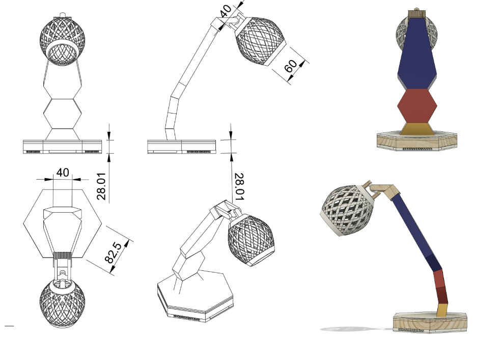
As the main frame of the lamp was angled forwards, I used Fusion 360’s centre of mass feature to find whether the point fell near the centre of the base of the object.
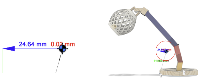
In the designs above, where the angle of the curvature is 12 degrees (on the mitre saw), the centre of mass is only 24.64 mm away from the edge of the base hexagon. It is also quite high at 84.88mm making it quite unstable and susceptible to tipping.
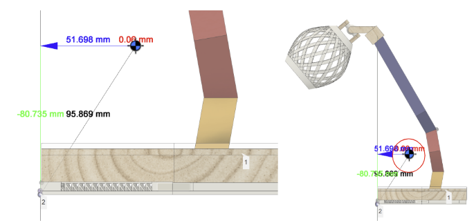
Thus, I changed this angle to 10 degrees which resulted in a much more stable configuration with the centre of mass located closer to the centre of the base at 51.99mm away from the centre and 80.80mm higher than the base. A lower centre of mass closer to the middle of the base ensures the product is less likely to tip which is particularly important when designing a product to be used on a desk.
Adjustable Lamp Joint
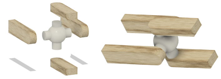
After trialling and testing, I discovered that the ball and socket joint exhibited limitations such as looseness and difficulty maintaining in the desired position. Additionally, the usability and functionality of the lamp was further reduced by the inconvenience of using threads for readjustment as it made it more challenging to achieve precise adjustments. This made it less practical for efficiently adjusting the light angle and direction.
To address this issue, I decided to research and change the joint to a more convenient and practical joint: a universal joint. The universal joint offers more flexibility where users can easily adjust the position of the lamp without the additional inconvenience of using threads for readjustment. I chose to add spring washers on each side, ensuring that the lamp maintains its desired positions with stability.
Extra Ventilation
An issue that could arise with this design is the heating of the base of the lamp. This poses risks to the functionality and safety of the ESP32 and additionally makes the lamp hard to handle and move around.
To address this issue, I incorporated better heat dissipation techniques. I did this by adding adequate ventilation to ensure sufficient airflow within the lamp’s base. This ventilation was provided by an extra 3D-printed compartment (using ASA) underneath the base of the lamp.
Final Design
Wireless Connectivity
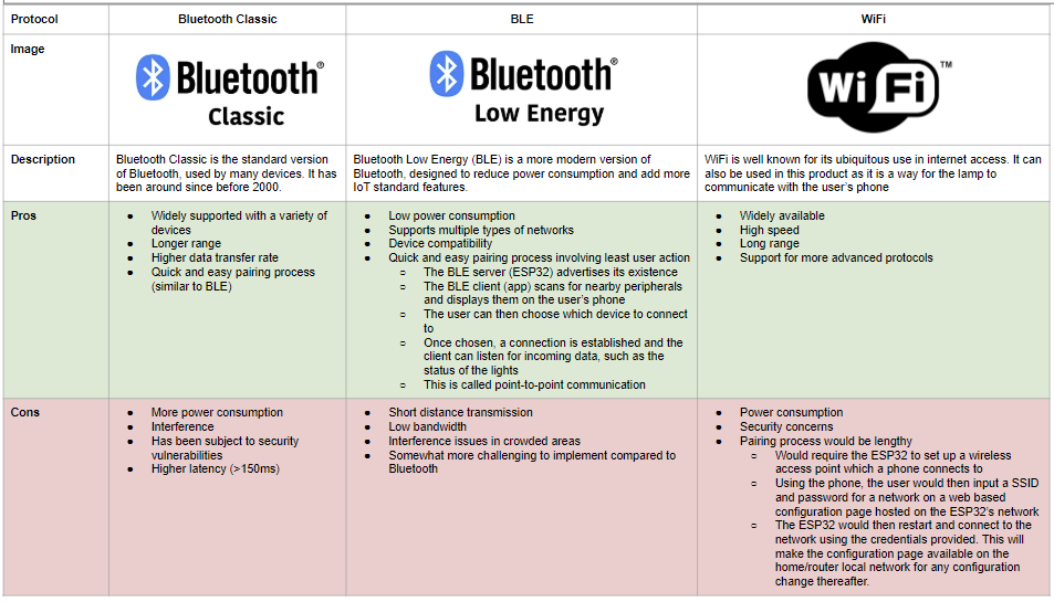
Given the advantages and disadvantages of these wireless communication protocols, I decided to use Bluetooth Low Energy (BLE) since it meets the energy efficiency requirements as it has low power consumption. In addition, it is low cost and is efficient for sending small packets of data, making it ideal for this purpose. Although BLE tends to have a short range, this is unlikely to hinder the end product as the lamp is designed to be used across the room/short distances.
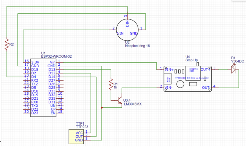
Circuitry
In the circuitry of this design, I wanted to be able to control a 45 LED Neopixel ring light (in the base of the lamp) and a 9 LED 5V Kitronik desk light (within the lampshade) using an ESP32. I decided to use an ESP32 as it is compact, making it easy to integrate into the design, and it supports Bluetooth BLE.
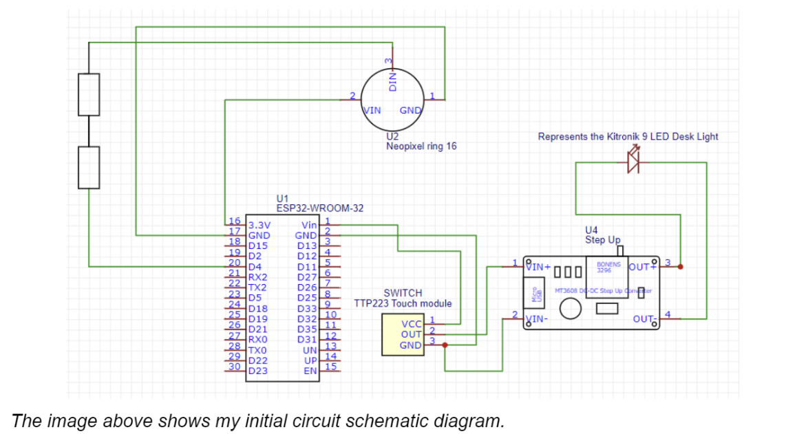
The diagram shows the connection with the Capacitive HTTM Touch Module (touch sensor) and the Kitronik 9 LED desk light (represented by the diode).
My initial circuit diagram (with only the manual switch having control of the main desk light) features a connection to a DC to DC step up voltage converter. This is in place as the output voltage of the switch is only 3.3V whilst the Kitronik Desk light requires 5V. Thus, to ensure that the light glows to its potential, I have increased the voltage between the switch and the main light.
App and Code
To code the app, I decided to use Apache Cordova, an open source platform for mobile app development, that uses standard web technologies e.g. HTML, CSS and JS. Thus, it allowed me to transfer my web development knowledge to make a mobile application that can be easily deployed on multiple platforms (Android, iOS). This also allowed for rapid prototyping and development of the app.
Code for Bluetooth Communication
In this scenario, the ESP32 acts as the BLE server as it advertises its existence so it can be found by other devices and wireless communication can commence.
For communication, BLE uses GATT (Generic Attributes), which is a Bluetooth profile where the service represents a collection of related data and each characteristic represents specific data values.
The mobile app’s javascript uses the cordova-plugin-ble-central3 to scan for other BLE peripherals. The user can then select a device to connect to through the app. Once connected, the app and the ESP32 can send and receive data through the different characteristics.
For unique identification, I have assigned the service and each characteristic a UUID which both the app and the ESP32 microcontroller use to distinguish the data/events.
Initialising the server from the ESP32 (Arduino):
 BLEDevice::init("ESPLAMP");
 BLEServer *pServer = BLEDevice::createServer();

 BLEService *pService = pServer->createService(SERVICE_UUID);
Using the BLE plugin in the app (JS):
ble.scan([], 5, app.onDiscoverDevice, app.onError);
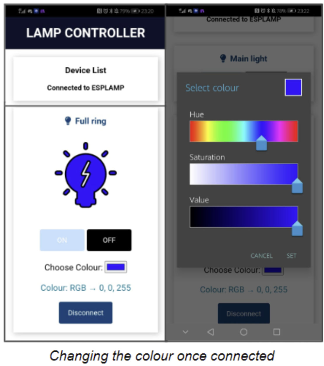
Code for changing colours/Switching the Light on or off
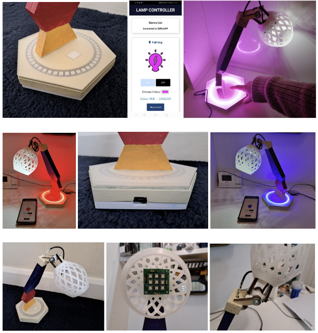
Once connected, I have developed an interface in the app that allows the user to switch the light on/off and change the colour using a colour picker.
If the user changes the colour, the change is detected using an event listener in javascript (this calls the getRGBColor function below) and the mobile app sends the data for each characteristic (colour) to the ESP32.
getRGBColor: function(event){
        var value = event.target.value;
        let  rgbv = app.hexTorgb(value);
        var deviceId = event.target.dataset.deviceId;
        let HexValue = document.getElementById("HexValue");
            HexValue.innerHTML = rgbv;
        app.setColor(deviceId, String(rgbv[0]), String(rgbv[1]), String(rgbv[2]))
    }
ble.write(deviceId, lamp.service, lamp.red, app.stringToBytes(red), success, failure);JS code in the mobile app
The ESP32 then listens for incoming data and, once data is received/changed, the ESP32 can read the data for each of the characteristics and reflect the changes in the ring light.
Code on the ESP32, Callback code for the red value of RGB:
class MyCallbacksRED: public BLECharacteristicCallbacks {
    void onWrite(BLECharacteristic *pCharacteristicRED) {
      std::string value = pCharacteristicRED->getValue();
      if (value.length() > 0) {
        char* redValue = strcpy(new char[value.length() + 1], value.c_str());
        writeFile(SPIFFS, redPath, redValue);
      }
    }
};
Note: the variable “statusvalue” in the code below refers to whether the light should be on or off
void loop() {
if(statusvalue=="1"){
for (int i = 0; i <= 44; i++) {
              leds[i] = CRGB ( redvalue.toInt(), greenvalue.toInt(), bluevalue.toInt());
              FastLED.show();}
}else
{
  for (int i = 0; i <= 44; i++) {
              leds[i] = CRGB ( 0, 0, 0);
              FastLED.show();
    }
  }
}
Code on the ESP32, Code to reflect the changes onto the ring light
Code for remembering the colours
I have also written code that implements data persistence, ensuring that the colour and other user-selected settings, such as the state of the lights, are stored in non-volatile memory locations to be remembered for future connections to the lamp.
In order to do this, I have utilised SPIFFS (Serial Peripheral Interface Flash File System), which is a non-volatile lightweight file system on the ESP32 that allows me to save data, such as files and documents, to the ESP32
To save the colour preferences and other settings to SPIFFS, I have used the “SPIFFS.h” library to save the characteristic values to SPIFFS in each callback.
Code in each callback:
writeFile(SPIFFS, redPath, redValue);
Reading from SPIFFS in the loop:
const char* redPath = "/red.txt";String redvalue = readFile(SPIFFS, redPath);
Code for automatic pairing
In addition to remembering the colours, I have also implemented code for remembering peripherals that the user has previously connected to. This allows the app to automatically connect to peripherals and immediately present the user with the interface for the lamp colours and settings.
To do this I have used the localStorage property which allows JavaScript sites and apps to save value pairs in a web browser with no expiration date.
Code for auto-connecting in the JS:
let conDeviceId = window.localStorage.getItem("ConnectedId");
console.log("Device id for autoconnect " + conDeviceId);
if(typeof conDeviceId != "undefined" && conDeviceId != null && conDeviceId != '' && conDeviceId == device.id){
app.connect(null, conDeviceId);
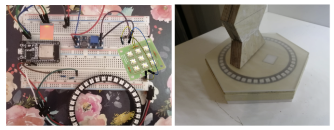
}Prototyping the Physical Structure
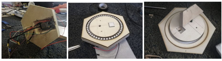
To accommodate the components, such as the ESP32, ring light and the touch sensor, I designed a robust base for the lamp that not only provides support but also incorporates dedicated space for these.
For the Neopixel ring light, I utilised a school laser cutter to precisely cut a hexagon and two concentric circles from a 3mm laser ply. This allowed me to create a fitting area for the ring light within the base, ensuring a secure and well-fitted placement.
To create a compartment for the ESP32, I used a router. The router allowed for the cutting of a precise space within the base that can comfortably house the ESP32, ensuring it is securely positioned.
Making the frame of the lamp
To make the frame of the lamp, I started by cutting out hexagonal shapes from a larger piece of wood. To achieve smooth edges, I utilised my school's belt sander to carefully sand down the cut surfaces, ensuring a clean and polished appearance.
I then cut out mitre joints along the lamp's frame and reinforced these joints with dowels.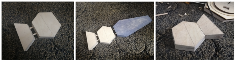
Making the top of the lamp
To create the lampshade (positioned at the top of the lamp), I utilised my at-home 3D printer. This enabled me to achieve a high level of precision and intricate detailing in the design.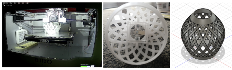
Some Issues Encountered
Issue 1: Lack of Operational Main Light
After finishing the soldering process, I observed that the main lamp at the top did not function at all, despite my repeated attempts. This led me to perform the calculations below and upon conducting these calculations, I discovered that the touch sensor had a current of 210 mA flowing through it. This current seemed excessively high and I concluded that it exceeded the capacity of the touch module and could have potentially caused it to malfunction.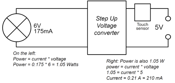
Improvement: changing the circuitry
Consequently, I decided to modify the circuit by incorporating an NPN 2N2222 transistor as a switch. By placing the touch sensor at the base of the transistor, a large current would flow through the desk light when the touch sensor is activated. This would also ensure that only a small amount of current flows through the switch, mitigating the risk of overloading it.
After more trialling and testing, I thought that it was inconvenient that one could only change the state of the top light through the lamp. Thus, I added another change in order to add the option of changing the state both manually and through the mobile application, where the phone can send BLE signals indicating whether the light should be on or off. The ESP32 can then use these signals to adjust the voltage on the base of the transistor.
The modified circuit is below:
In the main loop:
if (digitalRead(switchpin) == HIGH && switchstatebeingchanged==0) {
     switchstatebeingchanged = 1;
     toSwitchOnSwitch = true;
     toSwitchOffSwitch = true;
      startMillis = millis();
      if (mainlightstate == "1"){
          mainlightstate = "0";
          digitalWrite(ledpin, LOW);
       }
       else{
          mainlightstate = "1";
          digitalWrite(ledpin, HIGH);
       }
       writeFile(SPIFFS, mainstatusPath, mainlightstate.c_str());
      std::string mainstatusupdated(mainlightstate.c_str(), mainlightstate.length());
      pCharacteristicMAINSTATUS->setValue(mainstatusupdated);
    }
The modified connections of the physical circuit are shown below:
Issue 2: Intermittent Blinking
Although rare, there were occasional issues in the lamp’s lighting system with the lamp intermittently blinking and after various observations and intensive research, I came to the conclusion that this may be due to static electricity building up on the acrylic sheet, inadvertently activating the touch sensor.
Capacitive touch sensors are based on capacitors (adjacent electrodes which have capacitance with each other). In the sensor area, there are two layers of wire: the driving lines (bottom layer) and the sensing lines (top layer). The driving lines provide a constant electric current whilst the sensing lines detect the electric current. These layers are separated by an insulator in between. Electrons accumulate on the bottom layer, creating a negative electric field. This field results in the accumulation of positive charges on the upper layer. When a conducting material like a finger comes close to the screen, the electric field is disrupted. Thus there is a change in the positive charges on the upper layer, changing the capacitance.
When the touch sensor is repeatedly used, the contact can cause static buildup. This can also interfere with the electric field, changing the capacitance and leading to false touch signals registered by the touch module.
Improvement: Anti-static solutions
To improve this, I included an anti-static coating on the acrylic sheet which provides a conducting path and prevents the static from building up.
Finished Project
Here are some photos of the finished outcome: